
I am finally at the testing phase to check the functionality of the LSP-1 editor. This is the part where I become familiar with the dials on the front of the LXP-1 itself and check that all of my programming maps accordingly. It’s really important for ironing out bugs and getting the editor ready for release.
To complete the testing, I programmed in a temporary channel change program message dropdown. I will remove this at the end of the project because I do not like how you have to press the learn button on the front of the hardware and I do not wish to touch the Lexicon at all when my editor is up and running. I have already acheived full SysEX patch send and save through reversing the main 7-bit to 8-bit packing and then 8-bit to 16-bit conversions and back again, with a checksum. This route is fully remote and therefore, 10x better than holding a learn button each time which will be inaccessible when the Lexi’s are rack mounted.
Lets begin.
A useful LXP-1 algorithm summary can be found in the MRC manual (here), page 5-3.
Delay and Decay dials for the LXP-1 can be found be found on page 2-8.
A Quick Note for User Testing
TO DO: For anyone helping with testing, first off – thank you. Please let me know if there are any issues with the Left/Right channels coming out of the speakers. I flipped the diagrams to make L/R flow facing directly based upon the positions of the L/R in the algorithm block diagrams BUT the Chorus 1 test did not match the expected channel. It’s litteraly a case of twiddling the a dial on the left or right of the diagram and seeing if it makes a difference in the intended speaker and then add comments to the below. I will then fix.
If anyone has an MRC, please can you compare values from the editor, at the bottom of the dial, with the readout on the MRC display.
Chorus 1 also has a test note against it.
Everything else looks good.
Modulator Live Send Testing
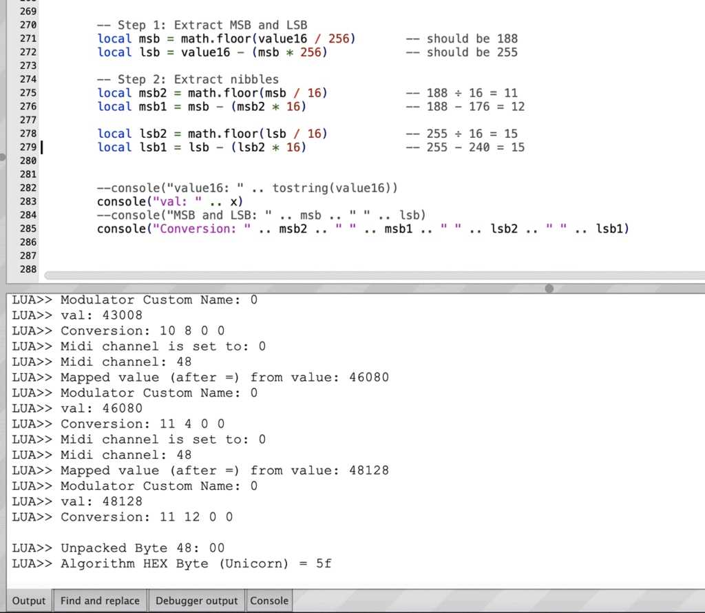
Console out was set to show all of the msb and lsb values during the conversion process. The 16-BIT values tally and the outputted HEX carried properly on the readout from MIDI Monitor. To test, I turn the dial on the the Lexicon and then use the hardware write option which involves holding down the Learn button and selecting a preset location from 1 to 128. The Lexicon flashes. I then load the preset location and check the output. The test showed my data conversion is correct but my channel output was incorrect. I updated the code to fix it and retested. It now works fine and the LXP-1/Reflex can be used for live automation.
Reverb – Hall and Room/Plate
Decay controls the Decay Mid Reverb setting.
Delay operates the Pre-Delay setting.
Top centre of circle (12’o’clock) is position 9 (slightly different to LXP-5).
| Test | Action | Result |
| 0. Value Collection | Collect 16-bit data for Decay dial 0. | (1) 32768, (2) 33792, (3) 34816, (4) 35840, (5) 36864, (6) 37888, (7) 38912, (8) 39936, (9) 40960, (10) 41984, (11) 43008, (12) 44032, (13) 45056, (14) 46080, (15), 47104, (16) 48128 |
| 1. Delay and Decay Knob | All LSP-1 dials turned to 100%. Function dial to Hall B. Decay dial to 0. Delay dial to 0. Save. | Feedback: Delay 1: All other algorithm parameters correct. (32768 | 32768) Correct |
| 2. Decay knob to position 16 | All LSP-1 dials turned to 100%. Function dial to Hall B. Decay dial to 16. Save. | Feedback: (tested below) Delay 1: (tested below) All other algorithm parameters correct. (48128 | 48128) Correct |
Decay range looks different on the LXP-1 and Reflex. 0.63 to 0.89 for the LXP-1 (MRC Manual) and 0.25 to 0.65 for the Reflex (p22, Reflex Manual).
Reverb Halls and Rooms
| Test | Action | Results |
| Small Room 1 | Turn function to Small Room 1 and record values from Decay Dial. | (1) 32768 (16) 48128 |
| Small Room 1 | Turn function to Small Room 1 and record values from Delay Dial. | (1) 32768 (16) 48128 |
| Small Room 2 | Turn function to Small Room 2 and record values from Decay Dial. | … Conclusion, the values from the 16 positions return the same 16-bit data. If there are subtle differences to ms, they are contained on the box itself. |
| Small Room 2 | Turn function to Small Room 2 and record values from Delay Dial. | No further tests needed |
Plate
Plate uses same ranges as Hall and Room. Values copied from there and therefore, no need for further testing.
Gate
| Test (Preset 8) | Action | Result |
| 0. Value Collection | Turn function to Gate and record values from Decay Dial. | |
| 1. Delay and Decay Knob *LXP-1 manual .25s Value, 0.19 – 0.45s Range (p2-10) but later, .150-390ms *Reflex .150-390ms | All LSP-1 dials turned to 100%. Function dial to Gate. Decay dial to 0. Delay dial to 0. Save. | All dials. Incorrect. Adjusted. Retested. (See notes) DECAY: Gate Time 32768 DELAY: Gate PreDelay 32768 |
| 2. Decay knob to position 16 | All LSP-1 dials turned to 100%. Function dial to Gate. Decay to 16. Save. | DECAY: Gate Time 48128 DELAY: Gate PreDelay 32768 |
| 3. Decay and Delay knob set to position 16 | All LSP-1 dials turned to 100%. Function dial to Gate. Decay dial to 16. Delay dial to 16. Save. | DECAY: Gate Time 48128 DELAY: Gate PreDelay 48128 |
Notes: I left a gap of three days and found a quirk. The values were not returning as expected due to a NULL value in the Source/Destination/Scale routing matrix. This led to values of 7FFFFFC0 and partially corrupted my SysEX string. To solve this, I used if statements to identify if the value was in the range (set) and if not, to change it to 00. This leaves CC0, Delay 1 – Coarse, Scale + x0.00. Delay 1 – Coarse is not sensible so will switch this to none (127). I then realised, I left Delay 1 – Coarse in place from the LXP-5. I therefore updated the mapping to meet the LXP-1 and then wrote a script to map in the parameter names from the algorithm.
Inverse
DECAY: Size
DELAY: PreDelay
| Test | Action | Result |
| 0. Value Collection | Turn function to Inverse and record values from Delay Dial. | |
| 1. Delay and Decay Knob | All LSP-1 dials turned to 100%. Function dial to Delay 1. Decay dial to 0 (6 o’clock). Delay dial to 0 (6 o’clock). Save. | All dials stored as expected. Size: 32768 PreDelay: 32768 |
| 2. Decay knob to position 16 | All LSP-1 dials turned to 100%. Function dial to Delay 1. Decay to 16. Save. | All dials stored as expected. *2 Size: 31 – value 48128 PreDelay: 32768 |
| 3. Decay and Delay knob set to position 16 | All LSP-1 dials turned to 100%. Function dial to Delay 1. Decay dial to 16. Delay dial to 16. Save. | All dials stored as expected. Size: 48128 PreDelay: 48128 |
*2 Manual states a maximum range of BE00 which in decimal is: 48640 equating to the full 32 step position. The LXP-1 maxes out at 48128. Conclusion being the editor can go one step beyond. Some may argue this is Madness.
The LXP-1 and Reflex have different Slope values from the manuals. Inverse for the LXP-1 on p4-18 shows a range of 16 steps. Reflex on p22 of the Midi Implementation Manual and Reflex User guide p27 has a range of 32 steps (1-32, NOT -15 to +15 like Resonator). On page 5-3 of the MRC manual, it states that the range of the LXP-1 is the same as the Reflex which is 32 steps at 1-32. Therefore, I conclude that 1-32 is more plausible and the LXP-1 manual on p4-18 refers to the main dial.
Ah now, that is pretty cool. While cross referencing with the MRC (which is a goldmine of useful information), I found that the LXP-1 presets were listed here on page 5-5.
Chorus 1
Decay: Feedback
Delay: Depth
| Test | Action | Result |
| 0. Value Collection | Turn function to Chorus 1 and record values from Delay Dial. | |
| 1. Delay and Decay Knob | All LSP-1 dials turned to 100%. Function dial to Chorus 1. Decay dial to 0. Delay dial to 0. Save. | All dials stored as expected. Feedback Negative = 0% 32768 Feedback Left = +0.2% 31744 Feedback Right = -6.1% 32768 Depth = 0.25ms |
| 2. Decay knob to position 16 | All LSP-1 dials turned to 100%. Function dial to Chorus 1. Decay to 16. Save. | All dials stored as expected. Feedback Negative = 94.1% 48128 Feedback Left = -93.6% 16384 Feedback Right = -99.9% 17408 Depth = 0.25ms |
| 3. Decay and Delay knob set to position 16 | All LSP-1 dials turned to 100%. Function dial to Chorus 1. Decay dial to 16. Delay dial to 16. Save. | Same as above Depth = 7.54ms with value 48128. [Will possibly come back to this] User feedback would be helpful. |
For test 1, turning to the dial to 0 offsets the left and right feedback. It is built into the algorithm. In the LXP-1 manual, p2-7 “stereo flanging with two flanges that move in a fixed relationship with each other”. Therefore, these values make sense. 94.1% (94%) is correct according to page 2-10. From the Reflex User Guide “This control applies slightly more feedback to the left channel than to the right.”. This comment is frustrating. According to the diagram on p24 of the Reflex menu, the left channel flows from the top, the right channel flows on the bottom. My right channel has more feedback than the left. This indicates these elements are incorrect in the manual. From the actual bytes:
| Description | Prog | Steps | Value Range | Converted Low | Converted High |
| Right Dly Feedback | 3 | 512 | 8000-BF80 | 32768 | 49024 (Extra Step) |
| Left Dly Feedback | 6 | 512 | 8000-BF80 | 32768 | 49024 (Extra Step) |
My console readout is as follows:
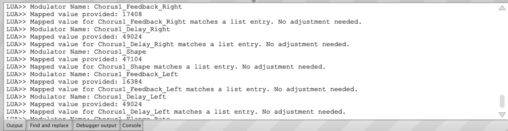
where Right Feedback on (3 -Right ) byte 7/8 is coming in at 17408 and (6 – Left) byte 13/14 is coming in at 16384 which is a lower value. Is this is mistake in the manual or update to the Lexicon v1.06 firmware? Only way to find out is to test. I do not have an audio card at the moment, so will rely on feedback.
There is a mismatch in the step count and hexiceimal range specified in the Reflex midi implementation for the Feedback Left and Feedback Right. These things are tricky to handle.
Step 511 + 99.5 %=49024. Value 49024 specified as the top range.
Step 512 + 99.9 %=49088. Value 49088 is the actual top value obtained following steps of 64.
Depth is set to 0.25 – 8.2 ms on page 2-10. From the Reflex manual, hex value BFC0 translates to 49024 for the maximum range for Depth. 7.54ms=48128. For Depth, there are 256 steps. “Delay xmit values above 0xBD00 (48384) are limited to 32000 samples, 1 second. LXP-1. Resolution of 128 reflects that machine screens the 1 second delay range to 8 msec intervals.”. Not sure what this refers to. The max limit from the MRC is 8.00ms. It’s tricky because the LXP-1 and Reflex share the same number of steps (Reflex Midi Implementation Manual) and range of .25-8.2ms on page 24 of the Reflex User Guide. It’s a pain (but also pretty cool) that the Lexicon will store well constructed 16-bit values because it makes testing a little harder. Ultimately, SysEx isn’t a dial and offers greater control. If the dial writes back to the editor (in this algorithm), slightly lower, it can be bumped up and it’s the first caveat for the editor. Everything else writes back as expected.
For users: I have set it to 512 steps and 49088. The final test will be, what happens when the dial is turned to maximum? If nothing happens then this value can be shaved off. If something happens, then either LXP-1 is rounding or it’s making an impact but the different in 0.3% is so slight – it doesn’t warrant a change.
Chorus 2
DECAY: Resonance
DELAY: Tuning
| Test (Preset 16) | Action | Result |
| 0. Value Collection | Turn function to Chorus 2 and record values from Delay Dial. | |
| 1. Delay and Decay Knob | All LSP-1 dials turned to 100%. Function dial to Chorus 2. Decay dial to 0. Delay dial to 0. Save. | All dials fine. Resonance: 48640 Tuning: 30720 Resonance (Unused) 32768 Tuning (Unused) 32768 |
| 2. Decay knob to position 16 | All LSP-1 dials turned to 100%. Function dial to Chorus 2. Decay to 16. Save. | Resonance: 48640 Tuning: 30720 Resonance (Unused) 48128 Tuning (Unused) 32768 |
| 3. Decay and Delay knob set to position 16 | All LSP-1 dials turned to 100%. Function dial to Chorus 2. Decay dial to 16. Delay dial to 16. Save. | Resonance: 48640 Tuning: 34560 Resonance (Unused) 48128 Tuning (Unused) 48128 |
Slope, 32 steps -15 to +15 (arbitrary units) p4-22.
Chorus 2 starts off a bit of a pain. Reading through p4-12 of the LXP-1 manual, the parameters are clearly laid out with Resonance Feedback and Tuning in slot 6 and 9. Head to the Reflex manual and Resonance Feedback and Tuning are in different algorithm slots (1 and 2). Head to the Reflex midi implementation manual and they are in the same slots as the LXP-1. Argh!
I will assume that they are in slots 1 and 2 until I hear back from users. The reason why this is a pain is because I’d prefer clean scripting to place the correct values on the correct location. 1 and 2 look correct because while importing bytes from the Reflex, slot 1 and 2 contain data. I’ll double check this when building the presets themselves. Slots 1 and 2 should be empty. If they contain data, I’ll know something is up. UPDATE: Well, I’m wrong. They contain the dial data and after testing, the dials are updating bytes.
Resonance feedback range is specified as -99…-87% to +87…+99% in the Reflex User Guide and 99% to -87% to +87% to +99% in the LXP-1 User Guide.
For Slope, LXP-1 manual on page 4-22 specifies the range -15 to +15, MRC on page 5-3 specifies this as -15 to +16 and the Reflex, page 26 specifies this as -15 to +15.
LXP1 manual, “Off to one resonator every 0.12 seconds.”. for shimmer, 16 steps. 0.12×15 = 1.8 seconds. MRC has Shimmer at 0-100. Reflex has this at 0 to 1200ms.
From the LXP-1 Manual, A. Master Resonance and B. Fine Tuning are operated from the front DECAY and DELAY dials. “Sets average resonance from 93% to 99%. Drives parameter #6 (Master Resonance Feed back) to positive values only.”. and “Fine tunes all twelve resonators -8 to +7 semi tones from normal to match the tuning of your instrument. The lowest resonator is normally set to 440 Hz. Drives parameter #9 (Tuning).” page 4-21 of the LXP-1 Manual.
Delay 1 Tests:
Parameter number 1 is not used (Typical dial number)
Decay controls the Feedback – Bi directional and 512 values.
Delay operates the Group Delay/Delay 1.
Top centre of circle (12’o’clock) is 9.
| Test (User 29) | Action | Result |
| 0. Value Collection | Collect 16-bit data for Decay dial 0. | (1) 32768, (2) 33792, (3) 34816, (4) 35840, (5) 36864, (6) 37888, (7) 38912, (8) 39936, (9) 40960, (10) 41984, (11) 43008, (12) 44032, (13) 45056, (14) 46080, (15), 47104, (16) 48128 |
| 1. Delay and Decay Knob | All LSP-1 dials turned to 100%. Function dial to Delay 1. Decay dial to 0. Delay dial to 0. Save. | Feedback: +0.2% 32768 (Incorrect) Group Delay : 0ms 32768 All other algorithm parameters correct. |
| 2. Decay knob to position 16 *”The DECAY control sets positive feedback around the third voice pair from 0 to 94% (±99% available through MIDI System Exclusive).”. LXP1 Manual page 2-7. | All LSP-1 dials turned to 100%. Function dial to Delay 1. Decay to 16. Save. | Feedback: +94% 48128 Group delay: 0.90ms 32768 All other algorithm parameters stayed the same. (48128 | 32768). Correct (Read *) |
| 3. Decay and Delay knob set to position 16 *”The Delay 1 parameter may be set as high as 623 milliseconds (803 milliseconds under MIDI System Exclusive control).”. LXP-1 manual page 2-8. See revisions to 1000ms from below. | All LSP-1 dials turned to 100%. Function dial to Delay 1. Decay dial to 16. Delay dial to 16. Save. | Feedback: +94% 48128 Group Delay: 623ms* 48128 All other algorithm parameters stayed the same. (48128 | 48128) Minor change needed. Retested – Correct |
On page 29 of the Reflex manual, Feedback 1 is connected to the feedback but it is references as feedback 3. On page 22 of the Reflex midi implementation, “Note that the parameter accessed by the MRC: FDBK3 fader is called FDBK1 in the Reflex User Guide.”. Which again checks out. Confusing doing the testing but that’s the point of testing. To document this quirks, check that they function correctly and discrepancies cleared up as best they can be.
Anyhow, I have tested, checked and adjusted. I then tested again, rinse and repeat. It looks good. My remaining question is – for the Range: Bi which go into negative values, how do you set these values through the hardware? or is it a case that you need an MRC (or the LSP-1)?
Delay 1 is confusing for another reason. “(Pre-delay, in effect), rough values in ms
0, 8.2, 16.4, 24.6, 32.8, 49.2, 57.3, 73.7, 98.4, 123, 164, 213, 279, 367, 475, 623.”. These numbers equate to the dial positions but “Also available as MIDI parameter #1, which can set finer values, still in 8.2 msec increments, between the larger step sizes.”. The Reflex manual specifies this can go up to 1000ms whereas the MRC manual specifies this reaches 803. Position 16 equates to 48128. According to the Reflex manual, the top value acheiveable is 49088 so there is definite scope for a top range. There is enough range to add in a maximum of 803 (or even 1000ms) pending how I calculate it. So the question is – MRC value or Reflex manual value? If I take steps of 8.2 msec, 8×127 = 1016 (128 with 0), 8×128 = 1024. Rounding to 1000 but with a step of 128 instead of 64 like the Reflex. I am using a midi parameter. For further confusion, “The Delay 1 parameter may be set as high as 623 milliseconds (803 milliseconds under MIDI System Exclusive control).”. LXP-1 manual page 2-8. I am using this as midi SysEx rather than the assignable midi parameter #1 (via Destination). Therefore, 803ms looks the best option. Absolute headache this part. Thankfully, I commented out the strings if I need to adjust it.
How does this relate to the Reflex. Well, Reflex can go to 63232 with steps of 64 (totaling 256 steps). After far too much procrastination, I suspect this is a difference between the two devices with the LXP-1 being 128 steps and 1000msec is the true value. If the Reflex can span 256, and ends up on 1612ms, then the figure would be 3.387 msec increments. Not quite half of 8.2 but in the ballpark.
Delay 2 Tests:
Decay controls the Positive Feedback AND Feedback.
Delay operates the Group Delay.
Top centre of circle (12’o’clock) is 9.
| Test (Preset 15) | Action | Result |
| 0. Value Collection | Collect 16-bit data for Decay dial 0. | (1) 32768, (2) 33792, (3) 34816, (4) 35840, (5) 36864, (6) 37888, (7) 38912, (8) 39936, (9) 40960, (10) 41984, (11) 43008, (12) 44032, (13) 45056, (14) 46080, (15), 47104, (16) 48128 |
| 1. Delay and Decay Knob | All LSP-1 dials turned to 100%. Function dial to Delay 2. Decay dial to 0. Delay dial to 0. Save. | Positive Feedback: 0.0% Feedback: +0.2% Group delay: 0.90ms All other algorithm parameters stayed the same. (32768 | 32768 | 32768) Correct |
| 2. Decay knob to position 16 *“DECAY control sets the amount of positive feedback generated around the longest tap from 0 to 94% (±99% available through MIDI System Exclusive).”. LXP-1 Manual, p2-8 | All LSP-1 dials turned to 100%. Function dial to Delay 2. Decay to 16. Save. | Positive Feedback: 94.1%* Feedback: +94.1%* Group delay: 0.90ms All other algorithm parameters stayed the same. (48128 | 48128 | 32768). Correct (Read *) |
| 3. Decay and Delay knob set to position 16 | All LSP-1 dials turned to 100%. Function dial to Delay 2. Decay dial to 16. Delay dial to 16. Save. | Positive Feedback: 94.1% Feedback: +94.1% Group delay: 255.30ms All other algorithm parameters stayed the same. (48128 | 48128 | 48128) Minor change needed. |
In conclusion, I am happy with these tests. 94% initially seemed incorrect but after reading through the LXP-1 manual, I can see that the value falls in the correct place. For the Reflex, I get a match at -99.9% to + 99.9% which matches a readout of -99% and +99%.
Hi!
I came across your Unicorn LSP-1 project and I’m very interested — especially in the Reflex support you’ve been adding.
My setup: I have a Lexicon Reflex that I’m trying to integrate with a Melbourne Instruments Roto-Control (motorized MIDI controller). The goal is real-time parameter morphing for spatial automation in my mixes — things like decay, pre-delay, damping changes synced to song structure. I’m running Ableton Live Suite 12, so VST3/AU integration would be perfect for my workflow.
Right now the SysEx barrier is blocking me from full CC control, so your CC→SysEx translation layer is exactly what I need.
A few questions:
How is the project progressing? Any timeline for release?
Will there be a price, or is it free/donation-based?
If you’re still in development — would you like a beta tester? I have the Reflex hardware, Ableton Live Suite 12, and a proper hybrid setup with Soundcraft M12 mixer — plus motivation to really put it through its paces.
Happy to provide detailed feedback, bug reports, whatever helps.
Thanks for building this — it’s filling a real gap.
Best,
Ivan