
In today’s blog post, I am documenting my build of the Gyraf SSL. This blog wll be a bit like a build diary and I hope to increase my knowledge of electronics throughout this project. As always, I need to preface this diary by stating clearly that I am learning. This is a document of my jounrey, how I build the project and what I learn along the way. This is not a guide! If you follow along, you do so at your own risk. Electicity can kill so stay safe and if you make a GSSL, get it checked out by a professional before switching it on. I certainly will.
Now that’s out of the way, lets continue with the story. On the hunt for a G-Comp, I realised they were out of budget. Gyraf’s kept coming up as a decent clone and so, I started to explore my own build on the cheap. As luck would have it, I managed to source matched DBX 202 black can VCAs from an old console at £25 a pop which I thought would be perfect for an authentic build, so bagged them and started the project.
For quick answers, I reocmmend using the huge GSSL help thread. In Google, you can enter site:groupdiy.com into the search and then your query to pinpoint an answer quickly.
To make it easy to read a specific section, click the tab to open up detailed information about my ‘getting started’ research, BOM lists and more. I will then but together a tabbed build section as I build it.
GSSL Research – Parts and Process
-
PCB
-
BOM
-
Resistors
-
Capacitors
-
VCA
-
Toroidal
-
Case
-
Meters
-
Facia
After researching various builds from the various GSSL step-by-step guides, I noticed that there were several variations of the board. I looked at the main board in stock from a range of suppliers and quickly identified the current revision of the board to be v7 as of 2026.
There are several locations where to purchase the boards from. In this case, Pusherman (link) looks like a good source for the UK and I picked up four boards. AudioKitchenPCB, Creative-Clowns and a few others.
Other sources included analogclassics.com in America (link).
Expansion boards can be source from locations above. for the UK, I decided to buy from an EU store called ProAudioGC. I bought the Turbo Boards and Super Sidechain Filter with Relay. I read that turbo boards are important for stereo imaging and super sidechain could be very useful.
From the guides, I started assembling the parts list and then comapred with my boards, meticulously counting parts. It was taking ages so thought – surely someone must have completed this step before me? and thankfully they have, many times over spanning over a decade.
I then found the Gyraf BOM, a resource pack from Mikael (link) and looked into components. The problem I had with most of these BOMs are that they are vague for a beginner. For example, in this project, I decided to start with something simple – resistors and then work my way up. Immediately, I had to scratch my head. I needed to understand the tolerance and wattage. Thankfully, a decent answer can be found here (link) and here (link) from 2017 and a 2019 BOM from Weiss (link). Being UK based, I am going to build a BOM for CPC.Farnell as they are a trusted supplier of precision parts.
It dawned on me that I then should find a more detailed BOM and things really started moving when I came across Greg’s BOM list (link). While some of the parts will have changed – what a starting point! In relation to this, the 0.25 watts have modern replacements at 0.6 watts. Time to ask my first question (link) and a link to a suitable resistor (link) at 1%, MF0207.
To make life easier – I am going to share my own BOM as I build it but please note – there may be errors (link) and my BOM questions will be posted here (link)
Lets look at the resistors. These can be places in any direction. Due to using original cans, I need to pay attension to %-markings. For the actual type of resistor for purchase, I’m going for 1% but 5% should be fine. Initially, I wasn’t sure about using 1/4 watt (0.25 W) or modern 3/5 (0.6 W). It turned out that 0.6 is fine with 0.6 watts being the modern replacements. I came to this conclusion due to asking my first question (link) and here is a link to a suitable resistor (link) at 1%, MF0207.
As tedious as this is – I have counted the resistors from the new revision 7 board – I’ll update this as I actually build it but for ordering – this is useful.
| Resistor Value | Main PCB | Control PCB | Total | Location |
|---|---|---|---|---|
| 10R | 2 | 0 | 2 | Under large PSU caps |
| 47R | 2 | 0 | 2 | Bottom Right |
| 68R | 2 | 0 | 2 | VCA |
| 100R | 7 | 0 | 7 | Bottom left/mid-left, near Output and between VCA output and Sidechain |
| 120R | 2 | 0 | 2 | VCA |
| 470R | 5 | 0 | 5 | Bottom left, near Output. Bottom right. |
| 820R | 0 | 1 | 1 | Cable area |
| 1K | 6 | 1 | 7 | VCA (4 & Outside Bottom 2). Control (right) |
| 2K | 1 | 0 | 1 | Right, near 10 pin header |
| 2K7 | 0 | 1 | 1 | Cable area |
| 3K9 | 3 | 0 | 1 | VCA (2) + Sidechain |
| 8K2 | 0 | 1 | 1 | Cable area |
| 10K | 10 | 0 | 1 | Near Diodes (1) Output (4) VCA (4) Sidechain (1) |
| 15K | 5 | 0 | 2 | Sidechain (1) Outside top VCA (2) Output (2) |
| 20K | 3 | 0 | 1 | Near diodes (3) |
| 22K | 8 | 0 | 8 | Top Left Input |
| 27K | 0 | 1 | 1 | Cable area |
| 33K | 1 | 0 | 1 | Diodes |
| 47K | 6 | 0 | 1 | Output, outside of VCA right. |
| 56K | 1 | 0 | 1 | Between VCA and sidechain |
| 68K | 0 | 1 | 1 | Cable area |
| 82K | 0 | 1 | 1 | Cable area |
| 91K | 0 | 1 | 1 | Right hand side |
| 100K | 3 | 0 | 1 | Sidechain |
| 127K | 0 | 0 | 0 | |
| 180K | 0 | 1 | 1 | Near release |
| 220K | 1 | 0 | 1 | Sidechain |
| 270K | 0 | 3 | 3 | Between release & attack tatio |
| 470K | 1 | 0 | 1 | Diodes/header |
| 510K | 0 | 1 | 1 | Cable area |
| 560K | 0 | 1 | 1 | Near attack |
| 620K | 1 | 1 | 2 | Sidechain, Control board, cable area |
| 750K | 0 | 1 | 1 | Control panel right |
| 1M | 3 | 0 | 1 | 10 Pin header (1) Outside botton of VCA |
| 1M2 | 0 | 2 | 2 | Near attack and left |
| 1M8 | 0 | 1 | 1 | Left |
| 3M3 | 1 | 0 | 1 | 10 Pin header |
| 3M9 | 0 | 1 | 1 | Left |
Notes: Difference between my table and the BOM.
100R, orignal list has 1 less.
10K, original has 4 less
15K, original has 2 less
27K, original has 2 more
47K, original has 1 more
100K , original has 1 less
127K, original has 1 more
Worth noting that are a chunk of polystyrene resistors on the board. I have seen WIMA used a lot but there are cheap TDK resistors available too. In the search, I used PET and looked at the PPN value. 50 or lower looked optimum but again, for reolicating an older build, most likely higher spec than needed. Through bulk ordering, the WIMAs were decent value so decided on these.
Diodes 5x 1n4148These are flow forward with black ring pointing to the tip with the arrow with a line across it.
Ceramic capacitors are 10p
Ceramic capacitors are 22p
Ceramic capacitors are 33p
Researching capactitors was tricky for the uninitiated. It’s easy to get drawn into the world of the audiphile when in reality, modern spec parts are well above the older spec.
I already new that Panasonic have a fantastic range of caps for FS, FR and FC series with FC being the long life versions. Nichocon have some stellar caps for audio (MUSE in particular)and there are a few other brands available that are well regarded.
However, it wasn’t possible to get all of the top caps in all of the configurations. Does this matter? not partocularly. What about voltage? I could see from lots of photos harvested from other builds that some users were using the Gyraf part voltage values, others were higher spec. For example, plenty of 63v 100uF and 63v 22uF. Again – why and does this matter?
Time for question 2 on the forums: link.
Jensenmann really helped to develop my understanding here and wade through the confusion. Key info included that the PSU contains the highest voltage (35V) with no benefit to make the cap voltage rating higher. If the part cannot be found at that voltage, you can go higher. “Everywhere else the circuits work with +/-15V, so 25V rating is fine.”.
and a good analogy to think of is:
After reading through various forums and Facebook posts, some people say that the modern THAT VCAs are better than the older DBX 202 VCAs (available in different variations), some people swear that the older ones are the best. Others say that there is no difference or little to no difference. In my case, I managed to get original DBX 202 black cans for very low prices which offered a simialr cost to new THAT VCAs. Pending on the type of VCA you buy, you may need to tune the VCA so that they are not distorting.
To understand the process, White Sea Studio have a really useful video at about 20 mins in, found here (link). From thw White Sea Studio video, the pots/restistors for adjust the VCA need to be either relocated to the bottom of the board or extended slightly, outside of the main board. Otherwise, the cans won’t fit.
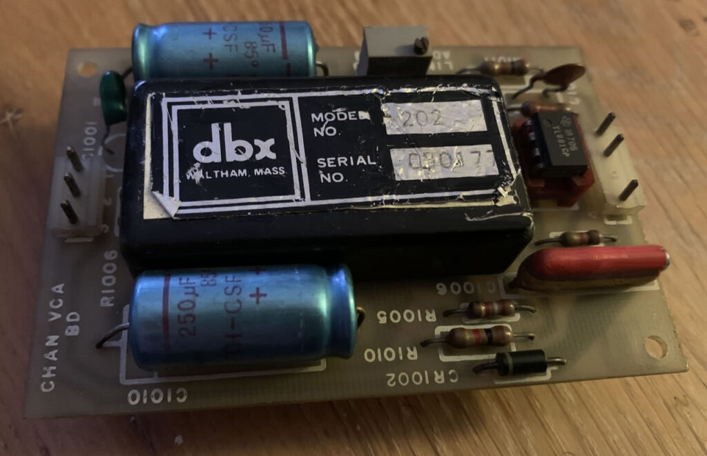
One thing to consider is the total costs of the DBX 202 VCAs versus the modern THATs. In my case, I found the parts at an equivalent price to the modern parts so thought – may as well go for it.
I found the Toroidal PSU tricky to understand at first because lots of photos show them without the mounting kit. When you read the product information, you it is likely that a kit is sent with the transformer. Inside my BOM, I found a few decent options.
An important consideration is the power rating. The original BOM has this at 10VA (I think) but to get the most out of the extras and addon boards, 25 VA is a good value. Other typical specs include primary voltage rating 115VAC/230VAC, secondary 15v to 30v and I went for the Triad version.
After reading extensively, a very important point is to ensure that the centre screw does not touch the top of the case. Some people dremeled this off, others put a plastic cap on the top.
The case is an interesting one. To make the compessor ultra cheap, I decided to buy a broken 1U rack item with a case that extends far back enough to fit the boards. If you can get something that already has a toriodal transformer mount, thats a real win.
I bought a faceplate to screw into the front from Pusherman and the faceplate screws fit one of the broken devices (BBE 362) but not the second AVX PDA500 Induction Loop. To make maters worse, I couldn’t help myself and fixed the BBE since it was a simple fix. In good conscience, I could not carve up a working bit of gear (defeats the purpose of my trying to help save the environmnet ethos) so had to put this back up for sale. I then bought a broken GGG LTD 3G mic mixer. The faceplate fit. All good.
After research, the basic meters used by the GSSL project are 1mA FSD (Full Scale Deflection) or 100uA. VU meters can be used with an expansion board but for the main purposes of the board, I think this will be find for now.
Useful information about the meters can be found here: link.
Parts for this are quite expensive and there are two types of meter. I ended up finding much cheaper parts from Alibbaba.com. I haven’t purchase from Alibaba before but the meters were so much cheaper that I decided to go for it and then measure again a meter from a confirmed source.
Not sure how these prices will hold over the long term but here are the links. Horizontal sliding meter (link) and classic VU style meter with a backlight (link). I’m not sure on the backlight colour yet but I hope it is the more expensive blue version. for the actual specs, I measured up again dimensions found on well regarded sites and these look like a match. I figured that resellers have to get their parts from somewhere so lets cut out the middleman prices. If when lined up with one of the middleman parts, the meters match, then they should be decent enough quality and at a good saving. When these parts arrive, I’ll check them overm take some photos, test and update this section.
My aim is for a high quality but cost effective build. It takes extra research to bring the costs down. No point over spending if you do not have to.
Facia, Dials and buttons.
Faceplate
I want to make a professional build but keep things ultra cheap. Therefore, I have thought about different appraches.
I could re-use the original panel for each box that I buy. The advantages are that the faceplate already fits. In order to do this, I need to get the dial values on the faceplate and fill in holes.
Options:
• Buy mulitple face plates. This can be quite costly and I have to pot luck second hand chassis cases for a match. So far, I have been 66% lucky.
• Custom panel cutting – exceptionally cool but more expensive (link)
• If holes are near the pots, I could use small washers or plates to cover the hole, held in by the pot’s nut. Aliexpress sell very small watchfaces that would do this job perfectly. Being as some of the watch faces have 12 dots, that works well for threshold and gain but not so much for ratio, attack and release. For these, I could use blank watch face plates.
• Other options were vinyl sticker sheets and a laser printer (link).
• To fill holes, I could use G-Weld, a can of spray paint and varnish.
• To go really cheap, I’m thinking of just blobbing on some black nail varnish or a combo of faces and black nail varnish.
Notes:
I bought one facia to to use as a template. The dial markings (dotted) are 32mm diameter and so a 28mm watch dial is not too far off and it will cover the holdes from the original faceplate. However, I have decided to the
Conclusion:
Being as I am building four, I am going for G-Weld expoxy to fill holes, light sand and spray paint. I will then drill new holes into the paint and dremel out any button spaces. I bought some cheap laser transparent printing vinyl paper from Label-Planet (£8) and created strips of authentic dials. For this, I went for 37mm diameter stickers since this will give me enough clearance to easily fit on the plate and something that should work nicey with autentic dials. I will then spray varnish to stop any of the ink from running. It won’t look as perfect as a custom plate but cost wise, £6 for the expoxy, £6 for the spray paint and £8 for the label set. £20. I already have drill bits and a dremel. Multiplied by four at £30 minimum for a faceplate, £120 so that’s a saving of £100.
While it may not be as immaculate as a custom build plate, it will look authentic and I doubt anyone would notice unless you look at it in the wrong light and even then, the transparent sticker locations will look neatly lined up and consistent. On the original, the names are nicely placed along the top. It looks very neat. To maximise the sticker, I have add the name of the control along the bottem which for a 37mm sticker, should be very efficient and look neat. I have quite a bit of experience designing GUIs from my software and I feel happy with the overall design. You get a lot of stickers for your money and I can see I’m going to have lots of sheets left over for many more projects.
What I like about this approach is that I’m really using every element of the broken hardware. It’s full on upcycling which means my impact on the environment will be much lower than getting a new plate manufactured and one of my goals throughout the site is to limit my impact ont he planet. Re-using parts is a fantastic approach, even pots from the older items if they are still good. I’ll wire with headers so if something breaks, it’s an easy replace.