
In today’s post, I look at replacing the battery in the Lexicon LXP series. Without a battery, the Lexicon fails to hold presets and you can experience other glitches. I bought a Lexicon with a leaky battery which had to come out quickly and one with a completely flat battery. As usual, this is my diary post for my own aide memoire. It’s not intended to be a guide because I am not experienced enough to offer guidance. I do document what I do so that I can learn and remember. I can ask questions and record answers. I can organise my own thoughts. Anything you do is at your own risk!
To begin, I watched my very own Lexicon opening video found here as a refresher:
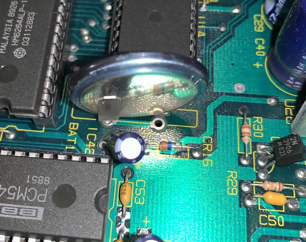
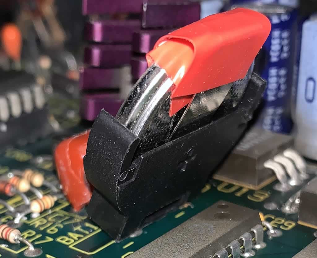
… and I looked for the battery in the board. It’s quite obvious when you see it. It’s like a computer battery, poking out vertically from the board.
For the LXP-5 series, mine all had glue gun glue around the holder and it was a pain to get off. I ended up soaking it in isopropyl alcohol (99%ish) and get it loose. I then carefully prized it away from the battery and board with a small, flat head screw driver.
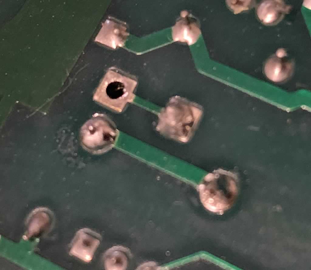
Next up, I used a desoldering iron to remove the battery. I bought a cheap one from AliExpress for £5 and it is ridicously good at sucking out the solder when you get your technique right. I practiced on an old Saphhire Pro board with leaky caps (which I repaied) before attempting the Lexicon so at this stage, a breeze. I was surprised at how efficient this was.
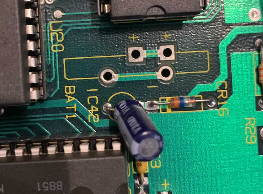
You can see my nice clean holes and they really are clean! Almost like a fresh board.
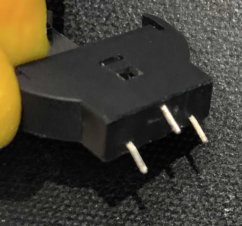
I then matched up the correct holder by reading through the fantastic post from Theresa at the Lexicon User Group (link). Theresa recommended part PN: BH-76A-1 Mfr: Adam Tech and I make an order (along with some LXP caps) from DigiKey.
Looking at Theresa’s photo:

the negative if facing forward. This is where I have paused. They positive legs fit the negative and the negative hole fits the positive.
The reason I paused is because when I worked on the Sapphire board, the capacitors has a positive (plus symbol) for the positive leg and negative (minus) for the negative leg. I compared with other capacitors. Nice and easy. This on the other hand has a negative symbol and a negative symbol where the two legs go but a positive symbol on the front.
Therefore, it sounds like it goes in this way and I solder all joints. My question is – do I reverse the battery in the holder? or not?
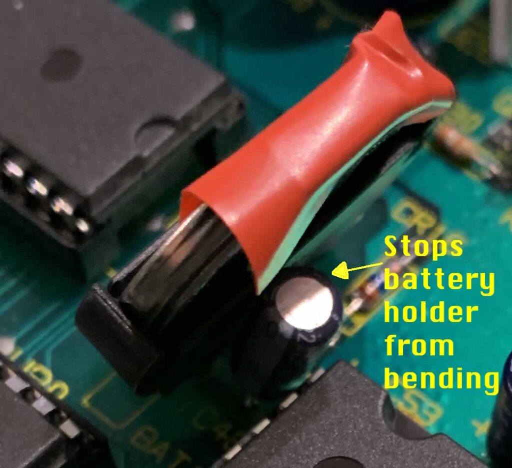
Thanks again to Theresa, any useful bit of advice, the battery holder will need to be tilted so that when the case closes, it can fit in there nicely. It adds a little extra height.
Update, as time went on, I obtained my answers.
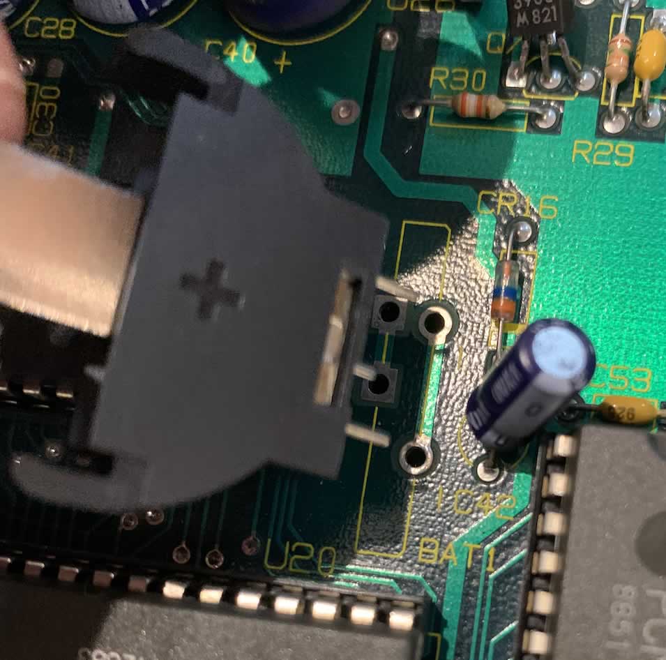
First off, I bent the lents on the battery holder and inserted a few times to check clearance. The legs on the holder had to be bent a lot more than I thought.
When it went into the board, I had to be careful that the small pin made contact. It was a lot closer to the board than the other two where the legs entered with greater depth. Ideally, a bit of glue gun would be a good idea for stability. Anyhow, at an angle, it looked like this:
I relation to the polarity, my thoughts were correct. I had to reverse the battery because the positive legs need to be soldered into the two negative holes.

After soldering, I added the battery and two layers of electrical tape. The battery had to go in the opposite way round to the terminal on the front. It went in positive at the front (where the negative symbol is located).
- Layer 1: Covered from the back of the battery, towards the top, to the front of the battery so that the clip containing the negative would not touch the positive.
- Later 2: Covered the top of the clip which would be positive. My toughts are, it’s just a bad idea to let the top touch the metal case. So I added a second layer of tape over the holder.
For the underside of the holder, I used some nice thick blobs of solder. I made nice clean contacts first of all. The technique used involved rotating the board vertically, holding the battery holder in one hand and blobbing a solder ball on the iron, in the other hand. I then blobbed the legs to get a hold on them. After getting enough to hold the legs in place, I then flipped the board upside down, so it laid flat but resting on a plastic block. I then used lead free Kester fine solder with no-clean flux to get into the holes, I got a nice and clean contact, filled and then blobbed the ends so that the battery holder felt firm. I chose no-clean flux inside the solder because it is not meant to be corrosive. I heard that other flux types like rosin can errode the traces in the board over time but cannot confirm.
Anyhow, I made nice clean contacts and nice clean blobs to hold it in place. Everything worked fine. I then checked the case clearance. I probably didn’t need the extra layer of tape but I cannot see it doing any harm.
There were some differences between the LXP-1 and LXP-5.
The LXP-1
The LXP-1 was pretty easy to do. All in all, straight forward.
The LXP-5
The LXP-5 had caveats.
- Case: Due to the location of the battery holder on the board, it hit the screw on the underside of the case. Thankfully, the cases can be flipped so the top became the bottom and vice versa. I am not screwing them into a rack so it makes little difference. Even cosmetically, as it’s half rack mounted, no-one will see it.
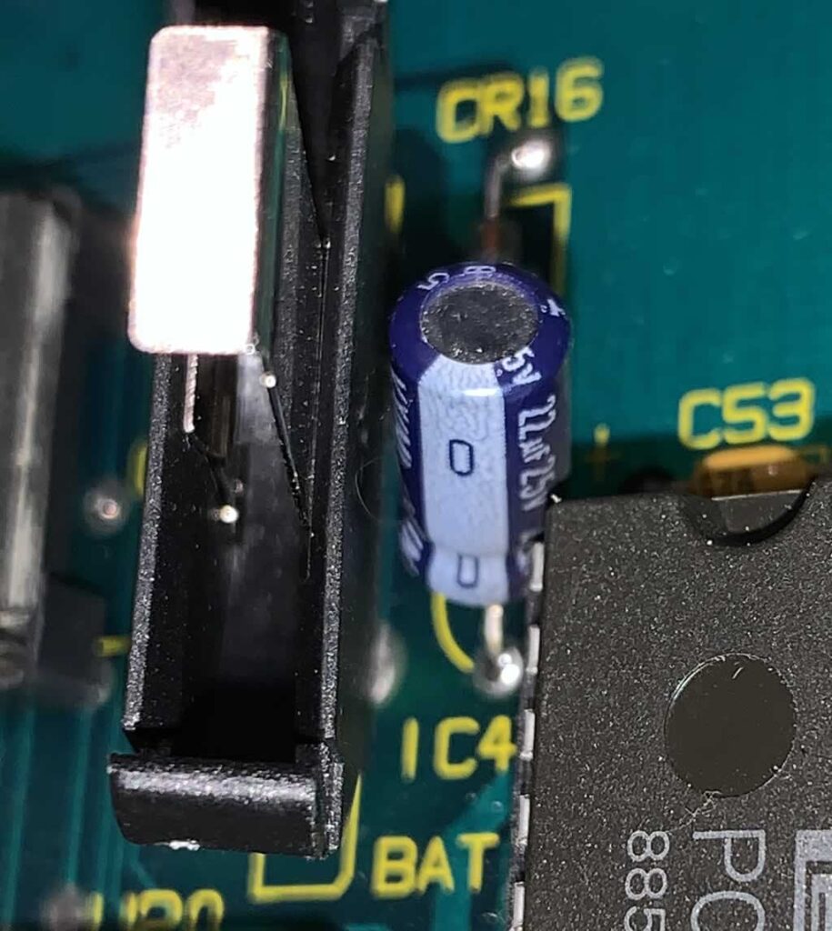
- Capacitor: Near the battery holder, there is a capacitor that can block the battery holder from sitting at a good enough angle to fit on the case. To make it fit, I had to carefully heat up my soldering iron and adjust the capacitor so that it sat at an sufficient enough angle to fit the battery holder in there.
In order to solve this problem, I had to resolder the cap and move it outwards at an angle slightly.
Conclusion
All in all, all four of my LXPs (2x LXP-1s and 2x LXP-5s) are working fine and with new batteries in holders. The main thing I didn’t like about the process was that it felt quite tough to push the battery into the holder. Each board made a brief crunching sound as it flexed ever so slightly. I tried a few different techniques to avoid this but coudn’t avoid pressure going onto the board. A direct solder would have avoided this but then, replacing the battery would also be a pain in the future.
The second thing I did not like was that bending the legs to slide into the case was also a pain to get right.
If I had to do it again, I think the LXP-1 would be straight forward but I would probably open up the LXP-5 first to see where if there is room to alter the angle of the capacitor near the holder. One LXP-5 had a greater length of leg running through the board which made the process easy. The other, not so. It took a lot of care to get it right.
All in all, my thoughts are that I would probably just swap the battery out with another soldered battery. It’s less hassle. I can see the merits of the holder if you are not good at soldering. The holder is awkward when inserting the battery and you need to support the holder and board while pressing the battery in to stop the board from flexing too much or else damage is possible. I think a gluegun would help here. The other advantage of a holder is cheaper, good quality batteries. I chose a well known brand with a guarantee that they will not leak. They were a lot cheaper than the solder on type, especially for the Lexicon due to the way in which the terminals are connected. It would have cost me approx £68.00 for four generic types that would fit or £10.00 for the holders and batteries from a well know brand. Well, the £58.00 is the price of another second hand Lexicon LXP-1 or 5 (at the prices I paid – granted – the needed a little work extra work) but still!
I can confirm that it works though and would give it a 7/10 in terms of investment of time and resources. I’m not keen on the holder but the price of the batteries swings it for me. If I could get the solder in batteries (from a well known brand) cheaper, I would prefer to solder them in. For the LXP-15, I’d use a battery holder because it’s a bigger pain to get the board out.
As an alternative, if a different type of battery holder for a smaller battery would work without bending and with legs that fit the terminals, I’d take that for convenience. Even if it meant having to swap the batteries out slightly more frequently. I would probably try this one (link) which includes a battery on a PCB.