In today’s blog, I am looking at the Klark Teknik DN3600 midi controlled graphic EQ. As part of my hybrid setup, I wanted some anlogue controlled EQ units that are controlled over midi. There are some really good options but this one looked pretty special due to the onboard software which means it can change it’s shape to fit two different types of fantastic, classic Klark TekniksEQ units. Real bang for buck. The question is, can it controlled by an app. We’ll I’m going to investigate. This blog is in two parts though because the DN3600 needs it’s own special midi cable to get running. This blog post will look at the cable.
A loack of standard cable is a pain in the butt. I repeat, the DN3600 does not use a typical midle 5 pin midi cable. Instead, it uses an XLR. As a result, I needed to start the project by soldering a midi cable to an XLR head. I chose a 6 metre midi/DIN cable so that I could cut it in two and add my XLR connectors, meaning two easy solder jobs with a good length of cable. The link can be found here. More often thn not, it’s better to buy a prewired cable with the most fiddly bits already done. Soldering 3 pins on an XLR is much easier than the rammed space inside the DIN lead head.
- 5 Pin 180 Degree Midi DIN Plug to Plug Lead, 6m – 5P-5P DIN SCREENED 6M
- Part: 5P-5P DIN SCREENED6M by ELECTROVISION
- Order code: AR70861
After chopping it open, I then used a multi meter set to continuity to work out where the pins line up with the cables for soldering. The pins are set as follows:
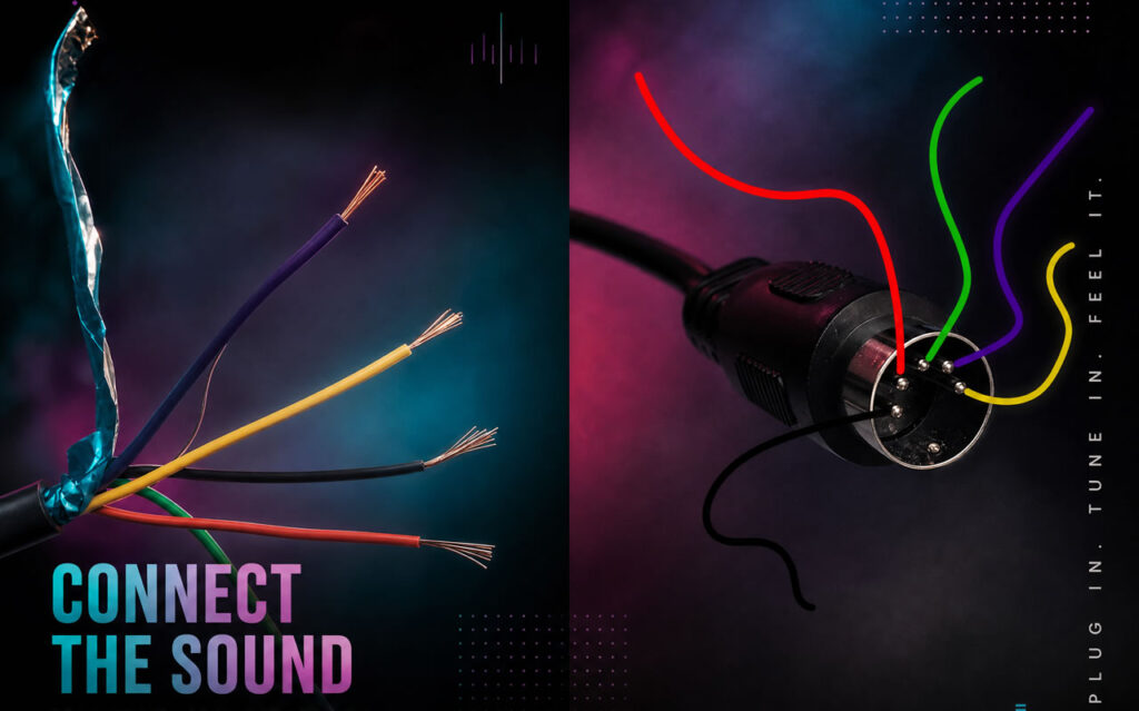
So, the next question is, how does this translate to the XLR cable? Let’s take a peak into the manual.
According to the manual, the “DN3600 Pro MIDI XLRs correspond to standard MIDI 5-pin DIN connectors”
| DIN | Signal | XLR |
| Pin 5 | – data – | Pin 3 (Red) |
| Pin 4 | – +5V – | Pin 2 (Purple) |
| Pin 2 | – GND – | Pin 1 (Green) |
Helpful, now lets look at which ones are classed as pins 1 to 5 for the DIN and XLR pins 1 to 3.
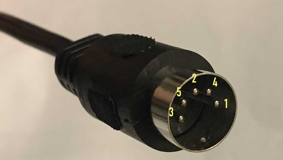
Okay, and for the XLR male?
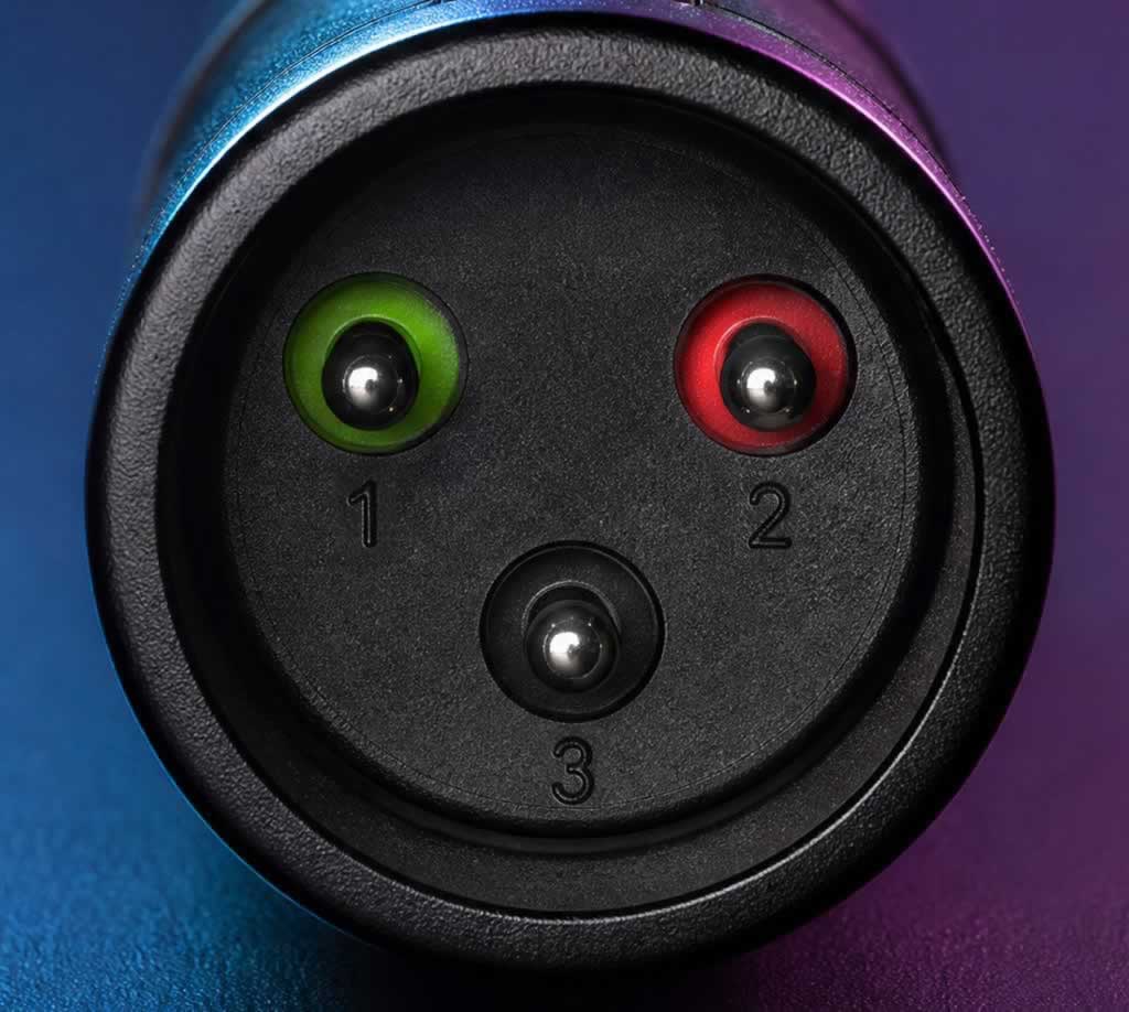
- 1 Green Wire
- 2 Purple Wire
- 3 Red wire
Okay, going to solder it all together than then look at what I can get out of the DN3600. If all goes well, I’ll create a ful up for part 2, where I can see what type of control I can get out of it and – where it will join my analogue, hybrid setup. Note that the female XLR has pin 1 and 2 reversed. It is important to look at the pin layout mapped when looking headon from the header you are using.
Update 1 (November)
So, how did it all work out? Painfully. I wrote code, performed tests, created various loopback configurations with data injection, read the handbook and service manual many times over. Something was not right? Did I have a broken unit? No idea. Could the DN3600 even handle midi? Where there changes in the last version of 3.01C firmware blocking midi? Time to pop the hood and start deciphering what was going on at a hardware level and solve this enigma.
Upon opening the case, I immediately recognised this fella which is used for midi handling. I came across this chip during a Peavey EQ repair (with a nasty Ni/Cadmium VARTA battery leak destuction) and the beige colour stood out. I have previously researched this chip and knew what I was dealing with here. Perfect! First bit of luck.
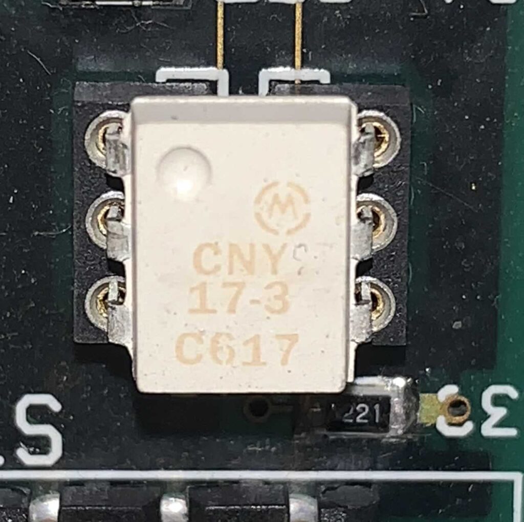
While powered off, I checked XLR connection continuity from the inside to the outside. All good, I then checked continuity from the XLRs to the chip via my multimeter. All good. I then ran some diode tests on the confirmed continuity pings and finally, some voltage checks. I sent a live loop of data from my Mac Book to the XLR input and measured the voltage spikes at the chip to work out if messages were being received. As the voltage danced on the meter, it all became clear. My wiring did not match up with the manual. I popped outside, and created a new midi din to XLR cable from the data and plugged it in. Exhausted by this stage, I was hopeful but not expecting much since I have already spent a week on this project. Voila! Beautiful, beautiful SysEx streaming from my output midi as I changed settings on the EQ. I no longer received the malformed mess. My conclusion was that the manual is actually correct. My DIN plug’s pins 4 and 5 were identified the wrong way round due to looking at the numbers from soldering view rather than front on. I have since updated my image for clarity. The left-to-right order flips between the front of the plug and the solder side. After a good length of testing, I now have the ability to control the DN3600, seeing data stream in it’s full glory. I can finally finish off my panel.
In part two of the blog post, I’ll add some photos of the wiring along with information about editor, VST and AU for this fantastic piece of kit. It should work for the D3601 too which means all of these amazing, classic DN3600s and DN3601s are going to get a new lease of life and the work here at monophreak will lead to less landfill and a better planet. More classic analogue beauty will be out there in the world. Machine by machine, slowly chipping away to a more carbon neurtral existence. No need to remake the wheel, we’ll be able to use this professional grade outboard gear in 2026 and with it;s secrets unlocked, going forward for the foreseable future.